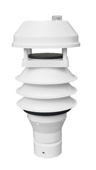
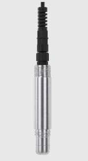
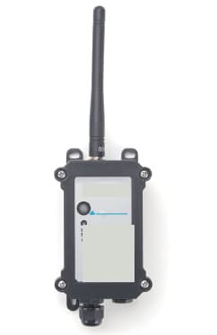
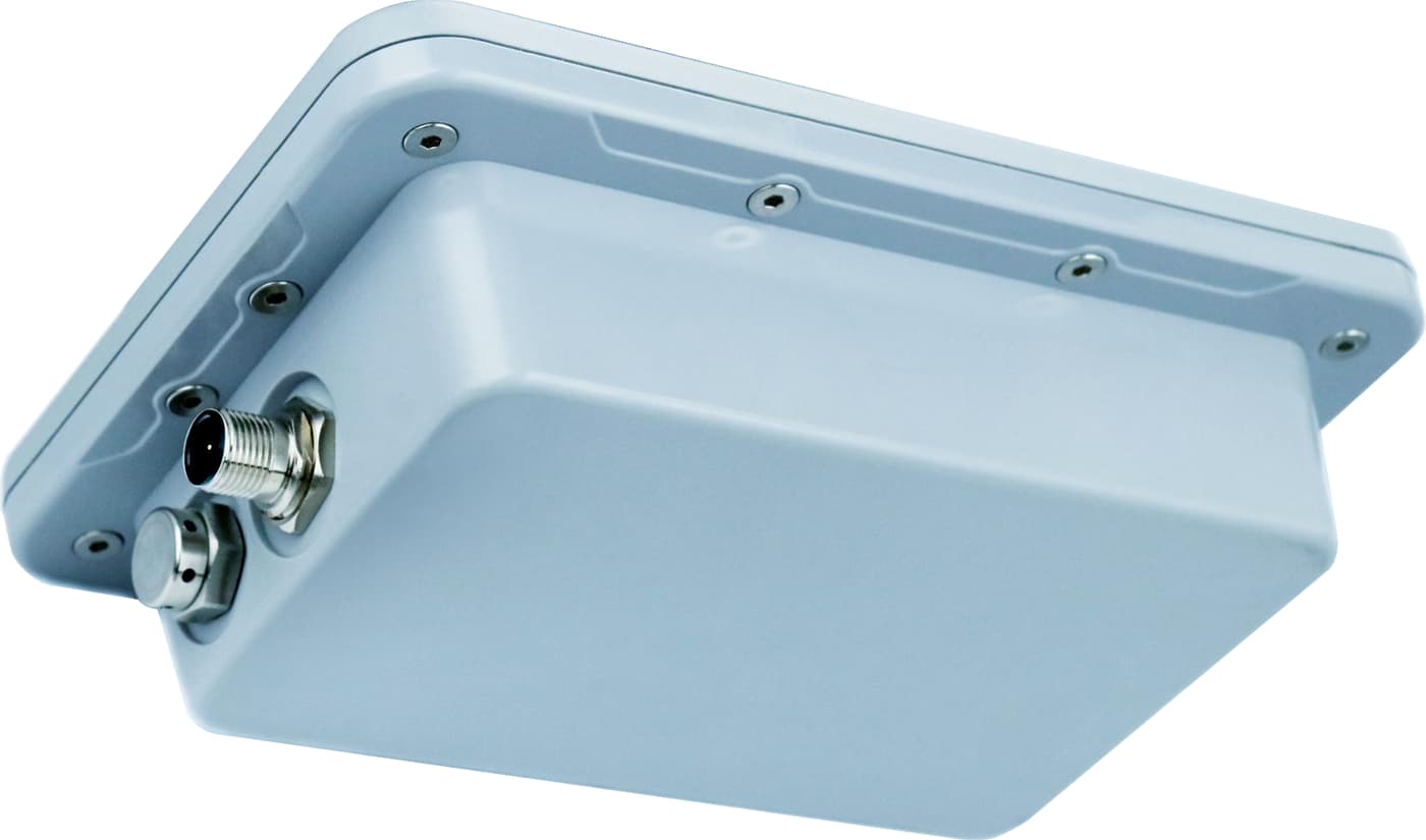
Check water available in wells and tanks, delivery from irrigation pumps, and pH or EC at water sources and mixing tanks. Select the measurement points, compatible inputs and data connection for your farm.
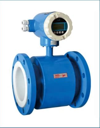
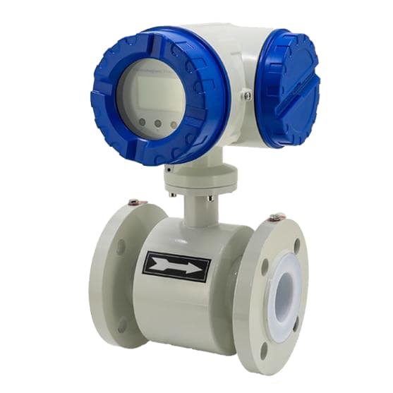
Pictured: SG-EMF-102 — Electromagnetic Flow Meter, Integrated and Remote.
Choose the farm water records your team will use
A well-level record answers a different question from a pH or EC reading. Select the measurement points first, then connect the instruments through compatible logger or RTU inputs.
Follow water available in a well or irrigation tank
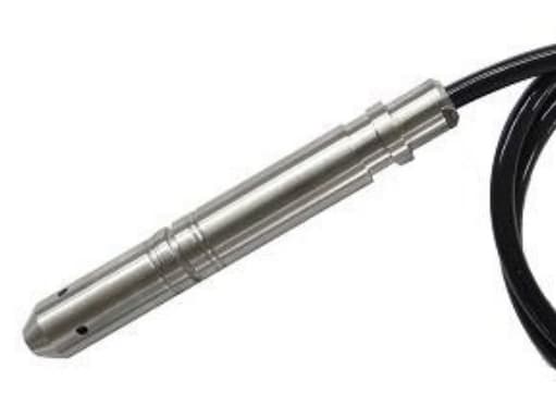
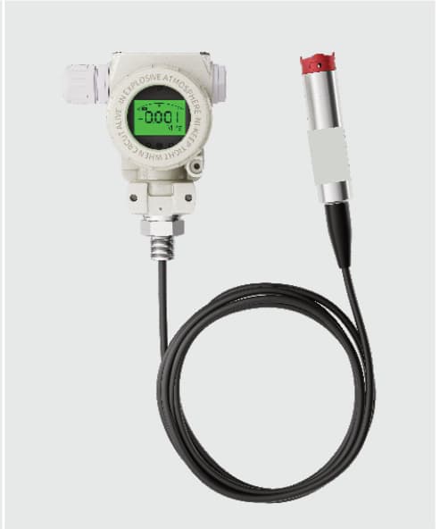
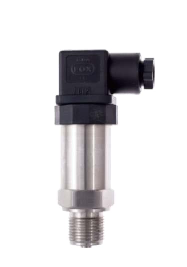
Record the level at the selected well, reservoir or storage tank. Choose the instrument from the depth, water conditions, mounting and cable route. Add flow or pressure measurements when you need to check irrigation delivery as well as water available.
Select water-quality points for irrigation or growing tanks
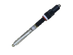
Use pH and EC readings for the water source or mixing tank. Add turbidity or dissolved oxygen where those are the measurements required by the application. Choose separate instruments or an integrated probe from the actual parameter list and maintenance access.
Start with the measurement point, then choose the connection
Water source and mounting
Provide the well depth, tank geometry or pipe arrangement, water conditions and a site photo. For water quality, include the liquid temperature and an accessible cleaning and calibration position.
Sensors and inputs
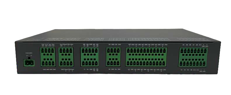
List the parameters and the selected instrument outputs. RS485 equipment needs compatible protocols and register maps; 4–20 mA instruments need matching analog inputs and power.
Remote records
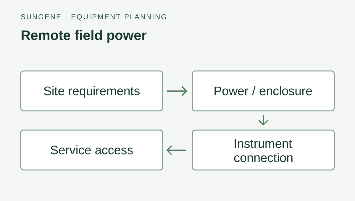
State whether records stay on site or go to an existing dashboard. Choose the separate cellular or LoRaWAN path and field power for that site. The quotation identifies the equipment, data connection and installation responsibilities.
What to send for a quotation
Send the farm country, number of wells or tanks, required readings and a site photo. Add the existing sensor labels, controller inputs and available power. State the network coverage and where the records will be sent. Request one measurement point or an equipment list for several sites.
Can I keep my existing well sensor or pH/EC instruments?
Send the instrument labels, outputs, supply and protocol documents with the receiving controller details. We can select the added equipment and data connection around compatible instruments. The equipment list identifies the instruments retained and the new items required.
Should I choose separate pH/EC probes or a multi-parameter probe?
List the parameters, measuring positions, water conditions and cleaning access. Compare the supported channels, outputs and mounting of the selected integrated probe with separate instruments. Include the compatible receiving inputs and calibration arrangements in the equipment request.
Water available, water delivered or water quality?
Choose the question your team needs to answer. Water level, pump delivery and water quality use different instruments; a farm can combine them through a compatible controller or RTU.
Country and well, tank, pond or irrigation-line location
Level, delivery or water-quality readings you need
A photo and any existing controller or sensor model
SunGene selects the equipment and data connection with the project team. Agree local installation, probe maintenance and the response to alerts before operation.
Irrigation flow measurement
Choose a permanent meter, a portable check or an existing signal
A continuous record on one pipe and a technician’s checks across several sites call for different equipment. Start with how the reading will be used.
Use an electromagnetic meter on a full pipe carrying electrically conductive water. Select the diameter from normal and peak flow, then match the liner, electrodes, flange and output.
Clamp-on measurement illustration; probe spacing follows the selected instrument.
Check several pipes during a site visit
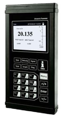
A portable clamp-on ultrasonic kit uses transducers outside the pipe. Record the outside diameter, wall thickness, material, liquid and mounting position for each water point.
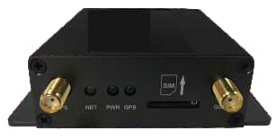
Pictured: SG-RTU-152 — Industrial Telemetry Remote Terminal Unit.
Bring an installed meter into the farm record
Keep the meter and read its documented pulse, 4–20 mA or serial output through a compatible logger or RTU. Match the units, scaling and totaliser records to the receiving system.
An irrigation supply line: plan the equipment together
Planning example for a farm drawing water from a storage tank into an irrigation line. It combines available water, delivered flow and line pressure in one equipment list.
Point identity, units and recording time for comparison
Use these records to compare irrigation runs and investigate changes in delivery. The site team sets irrigation schedules and maintains local pump protection.
For a quotation, send the country, pipe size, normal and peak flow, source-tank dimensions and any existing meter or pump-panel photo.
Add water-quality readings to your irrigation plan
Select the readings that support your daily work, then match the probes, mounting, controller inputs and maintenance access.
Irrigation supply and nutrient-solution tanks
Follow pH and electrical conductivity at the water source or mixing tank. Add level or flow measurements when the job also needs water availability or delivery records.
Measurements: pH and water EC; level, flow and pressure selected separately
Pictured: SG-EMF-109 — Electromagnetic flow meter for conductive liquids.
Which sensors should I start with for irrigation water?
Start with the decision the operator needs to make. pH and EC can follow water or nutrient-solution conditions; a separate level sensor, flow meter or pressure transmitter covers water availability and delivery. Provide the source water, crop or process requirements, expected ranges and existing controller inputs so the equipment can be selected together.
Should I select separate probes or a multi-parameter probe?
Separate probes let you place or service each measurement independently. An integrated multi-parameter assembly can bring selected measurements from one submerged point through a single RS485 connection. Compare the required modules, mounting space, cleaning access, calibration work and replacement plan before choosing.
Can the equipment connect to my existing PLC or monitoring platform?
Match each probe output to the receiving input. Depending on the selected product and configuration, the path may use RS485 Modbus RTU or 4-20 mA, followed by a separately selected RTU or gateway. Share the controller model, available inputs, register map or data format, site power and network before quotation.
The field requirement
Measurements and equipment on site
See available water, changing level, flow or pressure and pump status across remote farm water points. Agree whether the project is monitoring only or includes a separately designed control scope.
Who handles each part?
SunGene handles equipment sourcing, farm system architecture and the agreed software or integration work. On-site construction and installation are carried out by local teams; we can help you find and coordinate a suitable partner.
Monitoring a water point or connecting existing equipment
I already have sensors or a controller
Review the installed equipment and its outputs. We can assess adding data collection or transmission before recommending replacements.
I need a first monitoring point
Define the water-level and pump-status information you need, then select measurement, power and communication options.
Tell us the country, roughly how many water points and what you want to know. Water depth, power, network and platform details can follow.
Equipment and functions are selected for each project. Control work also requires agreed command authority, local protection and outage behaviour.
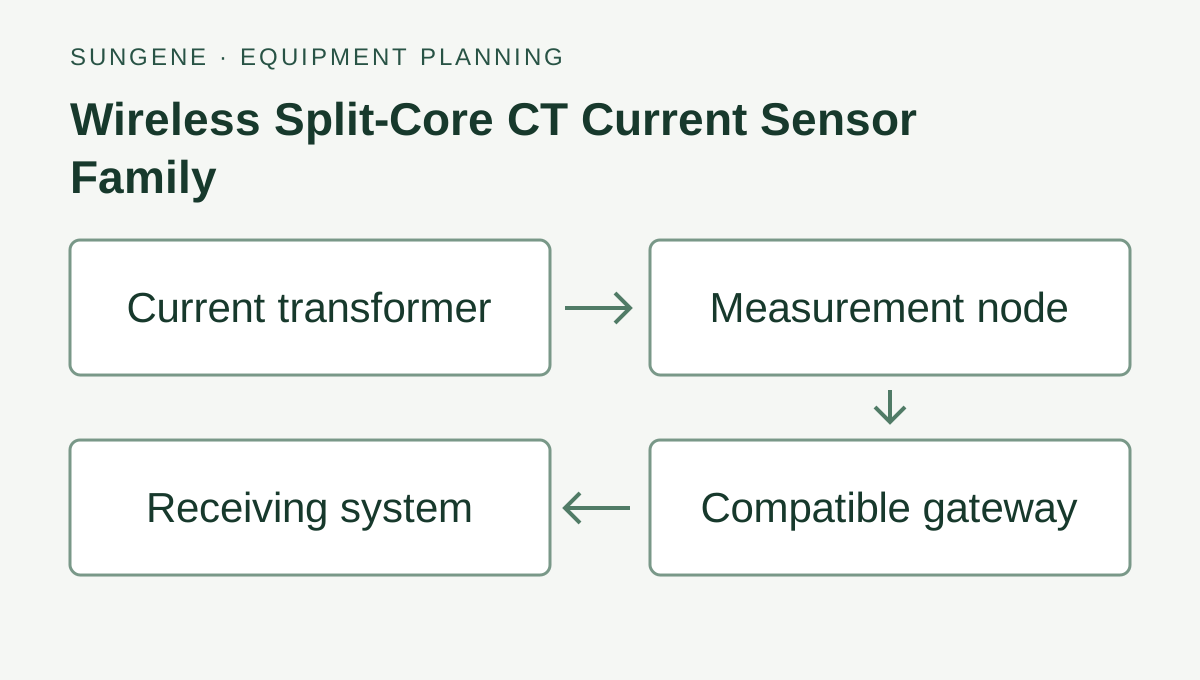
Level, flow, pressure and pump-status signals → logger or remote I/O → site network or cellular connection → shared data destination → agreed trends and alerts.
Choose the water signal, collector and data connection
Connect level, flow and pump-status readings through inputs matched to the installed instruments. Choose the power supply and network for each water point.
Sensor → collector → receiving platform
Measurement and signal
Collector and connection
Receiving platform
Measurement and signal
One remote water-level point
Select the level measurement for the liquid, depth and mounting.
Gateway → network server → payload decoder → receiving application. Verify point identity, units, timestamps and missing readings at the destination.
Country, roughly how many water points and what you need to know are enough for a first inquiry. Interface, power, network and platform details can follow during selection.
Check power, interfaces and installation conditions
Liquid, depth, pipework, mounting and access for maintenance
Pump-status signal, electrical interface and local protection
Grid or solar power based on the final station load
Network availability, outage storage and data backfill requirements
Working with what is already there
Review existing equipment for reuse.
Connect documented level, flow, pressure and pump-status outputs from the installed instruments to matching logger or RTU inputs. Send the device models and available interfaces.
Equipment, data connections and operating documents
01
Site and water-point assessment
02
Sensor, logger, enclosure and power configuration
03
Platform mapping, device identity and alert scope
04
Functional checks, recovery tests and operating handover
Your proposal lists the selected equipment, software functions, checks, site responsibilities and support. Share your existing equipment and site conditions so we can define the configuration.