Skip to content
SunGeneAgricultural IoT
← Agricultural solutions

Pumps, motors and agricultural facilities

Farm Pump, Motor & Energy Monitoring

Bring pump states, electrical readings and equipment-condition measurements into your farm record. Select individual devices or plan the equipment and data connections for irrigation pumps, greenhouse fans and farm buildings.

Plan farm equipment monitoring
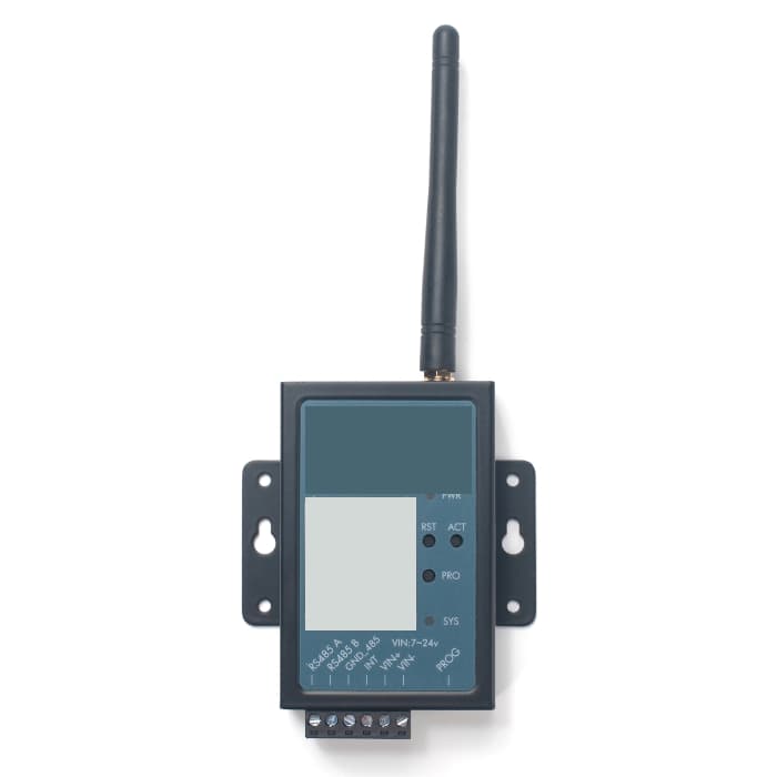
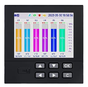
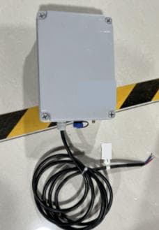
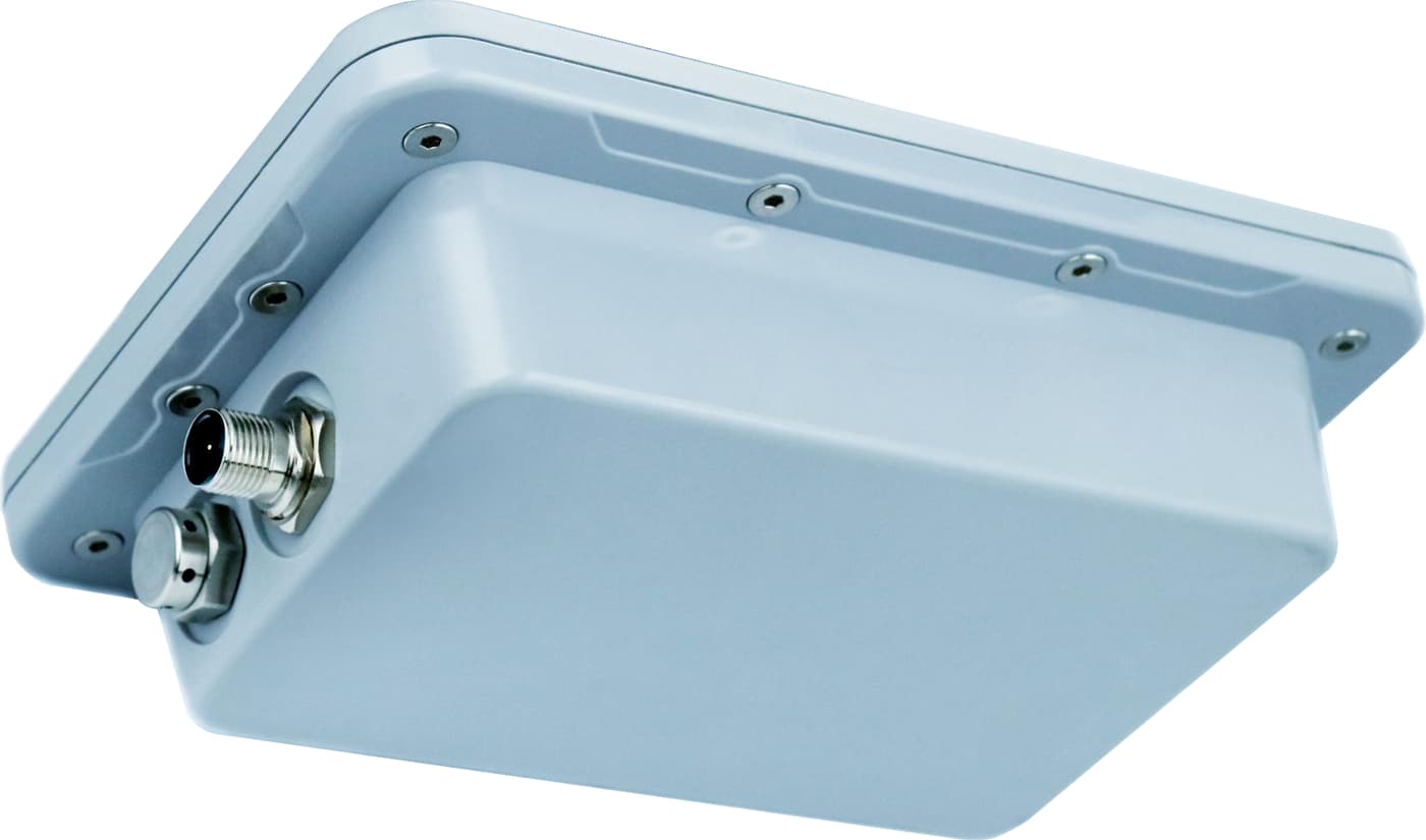
SG-RTU-145: Water Level Telemetry Terminal
Pictured: SG-RTU-145 — Water Level Telemetry Terminal.

Choose the measurement your team needs

A run contact, a current sensor and an energy meter answer different questions. Choose one path or combine the measurements in the farm’s receiving system.

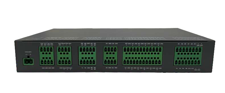
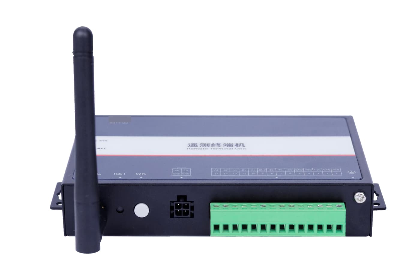
SG-RTU-152: Industrial Telemetry Remote Terminal Unit
Pictured: SG-RTU-152 — Industrial Telemetry Remote Terminal Unit.

See run and fault states

Follow when an irrigation pump, greenhouse fan or other farm motor reports running, stopped or in fault.

Equipment to select

Documented panel contacts or controller registers, compatible I/O and an RTU or logger with the selected network connection.

Data connection plan
  1. Run / fault signal
  2. Matching I/O and RTU
  3. Selected network
  4. Farm record

Select the input type and record equipment identity and time. Monitoring inputs stay separate from the start circuit and local protection.
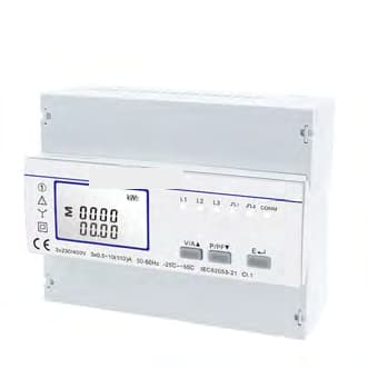
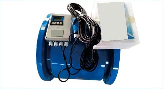
SG-EM-206: Three-Phase DIN-Rail Multi-Tariff Energy Meter
Pictured: SG-EM-206 — Three-Phase DIN-Rail Multi-Tariff Energy Meter.

Compare current and metered energy

Track motor load, or obtain kWh and other documented meter readings for pumps, fans and farm buildings.

Equipment to select

An energy meter for energy readings; a separate current measurement for load trends. A wireless current sensor needs its matching receiver.

Data connection plan
  1. Meter / current sensor
  2. Documented output or receiver
  3. Compatible collector
  4. Readings with units

Choose the circuit, phase arrangement, CT or direct connection and receiving interface with the local electrical team. Current alone is not kWh.

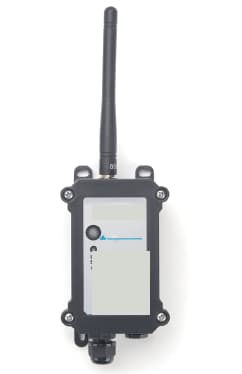
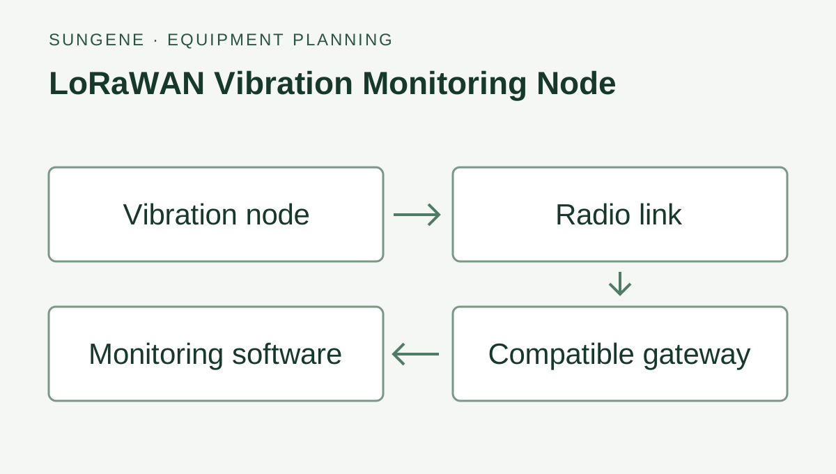
LoRaWAN Vibration Monitoring Node: Vibration node → Radio link → Compatible gateway → Monitoring software.
LoRaWAN Vibration Monitoring Node — connection diagram.

Follow vibration and temperature

Add condition records beside selected farm pumps or motors and compare readings with their operating state.

Equipment to select

A vibration node and the matching LoRaWAN gateway, network server and payload decoder, followed by the agreed receiving platform.

Data connection plan
  1. Vibration node
  2. Matching LoRaWAN gateway
  3. Network server + decoder
  4. Condition record

Match the radio region, mounting, reporting interval and enclosure operating limits. Use the records for review; do not treat one measurement as a fault diagnosis.

Send a photo and the question you need answered

  • Country, number of pump or equipment locations, and what each one does
  • Run or fault status, current, metered energy, vibration or temperature readings needed
  • A panel or equipment photo, available power and network, and the person receiving the data

From a device purchase to a farm project

  • Equipment list with the selected inputs, interfaces, power and network
  • Measurement names, units, equipment identity, timestamps and missing-data handling
  • Agreed software or platform connection, functional checks and configuration handover

SunGene plans the equipment and data path, supplies the hardware and handles the agreed software or integration work. Local teams carry out cabinet wiring, installation and electrical protection. The proposal sets out the work and support for each team.

Farm equipment monitoring questions

Can we keep the pump panel or controller already installed?

Yes. Start with clear photos, the controller model and the available interface documents. Select compatible inputs for approved run and fault contacts, analog signals or documented controller registers. The local electrical team retains responsibility for the start circuit, interlocks and pump protection.

Does a current sensor measure energy consumption or irrigation flow?

Current describes the electrical load. Metered energy requires a suitable energy meter and its documented readings. Water delivery requires a separate flow measurement. Keep these measurements and their units separate in the receiving system.

Can we buy individual devices or ask for a complete farm monitoring plan?

Both are available. Request a single meter, sensor or RTU, or an equipment list covering the field measurements, collection, communications, power and agreed software connection. The quotation defines equipment, integration, installation responsibilities and handover.

Does a vibration node diagnose pump failure on its own?

The node supplies vibration and temperature records for review alongside operating conditions. It does not establish the cause of a fault or replace the pump’s local protection. Agree the reading interval, missing-data indication and alert response with the receiving-system operator.

The field requirement

Measurements and equipment on site

Identify equipment, operating hours and useful measurements. Panel work and protection are coordinated with the qualified electrical team.

Who handles each part?

SunGene handles equipment sourcing, farm system architecture and the agreed software or integration work. On-site construction and installation are carried out by local teams; we can help you find and coordinate a suitable partner.

System architecture & engineering details
  1. 01Field sensingSoil, weather, water & equipment
  2. 02Data acquisitionInputs, mapping & field power
  3. 03ConnectivityWired, wireless & recovery
  4. 04Platform integrationYour platform or a suitable service
  5. 05Alerts & decisionsAgreed views, exports & workflows
Equipment and functions are selected for each project. Control work also requires agreed command authority, local protection and outage behaviour.

Approved status signals and meters → acquisition → network → platform → history and anomalies to review.

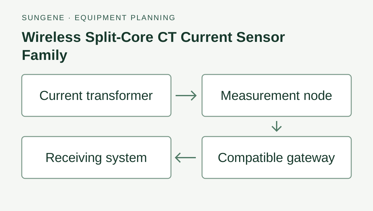
Wireless Split-Core CT Current Sensor Family: Current transformer → Measurement node → Compatible gateway → Receiving system.

Farm Equipment: Run Status & Energy

Track pump and fan run contacts, current or energy use. Select the signals available at each farm panel and the records your team needs.

Site & interface review

Check power, interfaces and installation conditions

  • Approved circuits and measurement points
  • Signal type and available interfaces
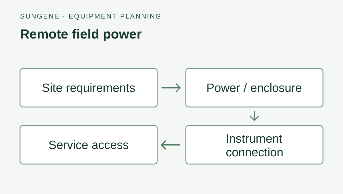
  • Power, enclosure and environment
  • Units and ownership of alerts

Working with what is already there

Review existing equipment for reuse.

Existing equipment can remain in service. Signal access and the connection method must be documented before changes are made.

Review equipment compatibility

See where the system fits

Our project role

Equipment, data connections and operating documents

01

Equipment and signal inventory

02

Approved interface and power review

03

Data mapping and agreed alerts

04

Functional checks and configuration handover

Your proposal lists the selected equipment, software functions, checks, site responsibilities and support. Share your existing equipment and site conditions so we can define the configuration.

See our integration services

Useful before you begin

Related installation and selection guides

Related equipment families

Equipment for this system

Select the version for your controller, power and site.

Contact SunGene

Ask about equipment,
planning or a system fault.

Tell us your country and what you want to measure or fix. A site photo or equipment list helps us check the options.