Follow changes in irrigation pumps
Compare machine readings over time with operating hours and maintenance records. Installation and the selected measurement determine what the trend can tell you.
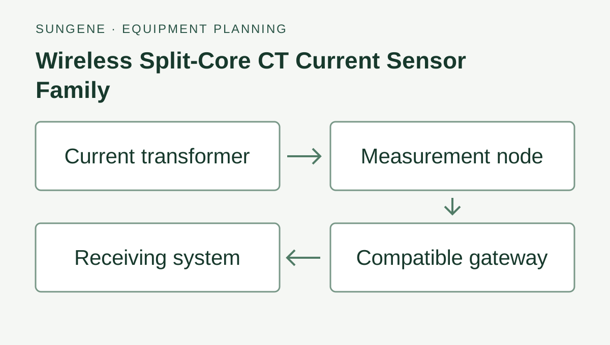
Wireless Split-Core CT Current Sensor Family — connection diagram.
Non-invasive wireless current sensing for retrofit load monitoring, with single-phase 100 A / 300 A and three-phase 300 A / 500 A / 1000 A configurations.
Related application hardware: Farm pump & energy monitoring
Compare machine readings over time with operating hours and maintenance records. Installation and the selected measurement determine what the trend can tell you.
Farm maintenance teams can monitor compatible pump motors and ventilation fans. A change in a reading needs investigation; it does not by itself prove a specific fault.
The quotation lists the selected equipment, accessories, price and delivery terms.
Purchasing and delivery details →Selection guidance and application documents. Wiring, register maps and certificates must match the chosen model and version.
English · Web page · printable
Online selection guide
Application selection guide
PDF · English
Tell us which wiring, protocol or calibration documents you need for the equipment.
Compare uses, interfaces and configuration options. These are selection references.
Define the required function, interfaces, power, mounting and accessories for the site.
Confirm the exact model, configuration, photograph, document revisions, accessories, price, delivery and warranty.
Tell us what you want to measure and where. Send a model number or site photo if you have one.
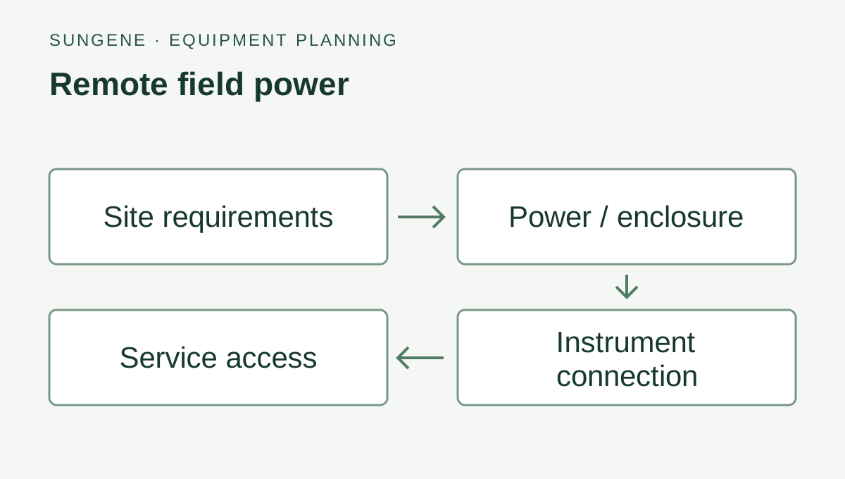
Size field power around the final equipment load, seasonal sunlight and visit interval.
Read the guide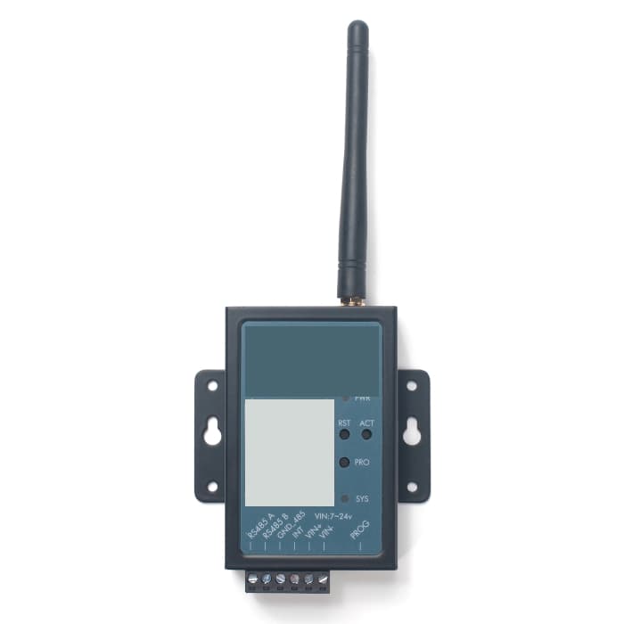
Check power, terminals, interfaces and data interpretation when readings are missing.
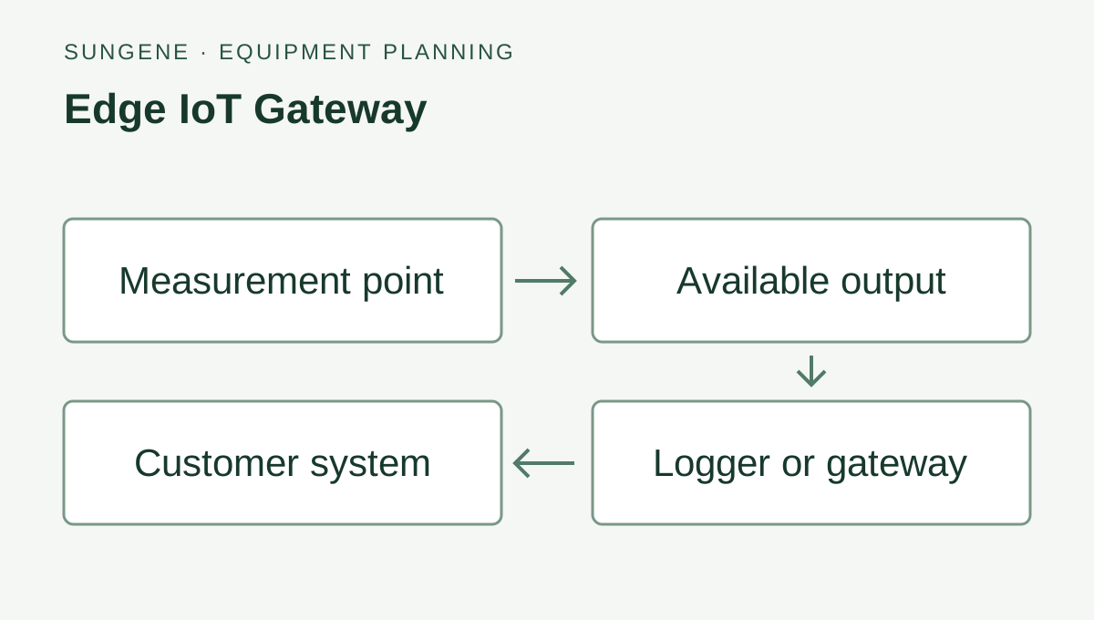
Read the guideExample equipment arrangement. Check compatibility and agree who handles software, PLC/SCADA programming and site installation.
Data destination
Customer platform or an agreed third-party service
Compare power, communication and equipment requirements for irrigation, pumps, soil and weather monitoring.
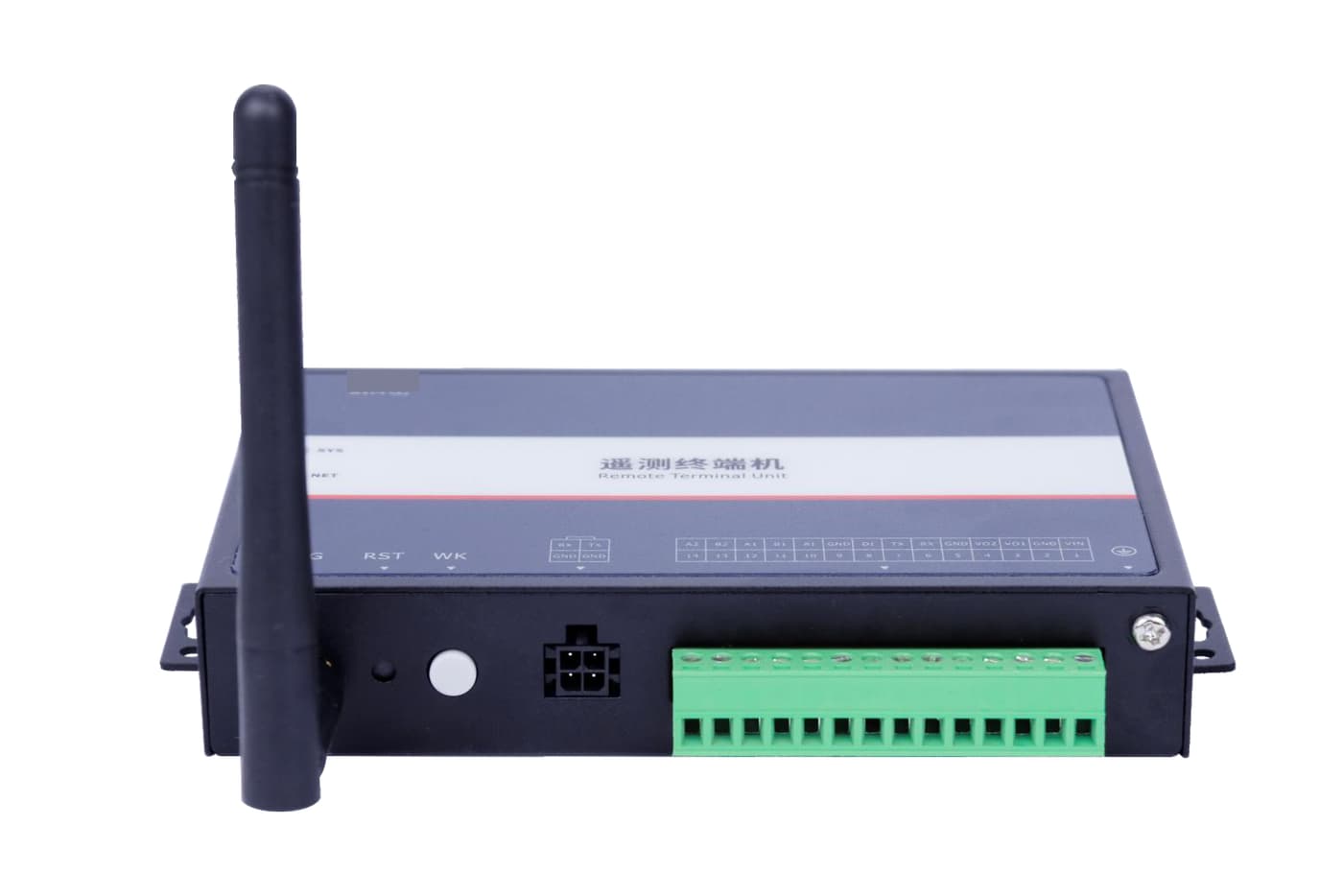
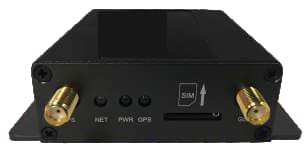
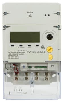
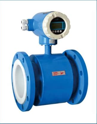
Product photograph
Pictured: SG-RTU-145 — Water Level Telemetry Terminal.
This sensor family has several configurations. Confirm the model, output and measuring range when ordering.
Compare related equipment and connection options.
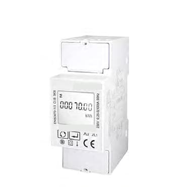
This is a configurable wireless split-core current-sensor family, not one universal stock model. Select the phase count and current range first, then confirm the conductor aperture, power option, regional radio path, gateway and reported data before quotation.
This family measures current and accumulated amp-hours. Estimating power also requires voltage and power factor. For billing or revenue metering, select an energy meter with the required documented accuracy and approvals.
The split-core construction is intended for non-invasive retrofit installation without disconnecting the existing wiring. Electrical isolation, safe access and local installation rules still apply.
Available configurations include 100 A and 300 A single-phase configurations, plus 300 A, 500 A and 1000 A three-phase configurations. Select from the actual conductor, normal current and peak current.
The source identifies a wireless current-sensor family, but the final regional radio plan, gateway, payload and destination platform must be confirmed for the project before quotation.
No. Sampling rate and measurement accuracy are different specifications. The product documentation lists sampling up to 3.3 kHz but does not publish a percentage accuracy class, so accuracy must be confirmed for the selected configuration.
That is a common retrofit path. The CT clamps around an existing conductor and a remote I/O, meter or LoRaWAN node forwards current or run presence. Conductor size, current range, phase count and whether you need kWh or only run/load must be confirmed before quotation.
No. This family is for monitoring and alarms into the buyer’s platform. Machine protection, certified safety circuits and trip settings stay with the existing starter or drive. Sampling interval and alarm delay are set from the maintenance workflow, not from a protection-relay standard.
Use the listed inputs, power and protocol to match the device to your controller. Send its model or an input photo with the equipment request.