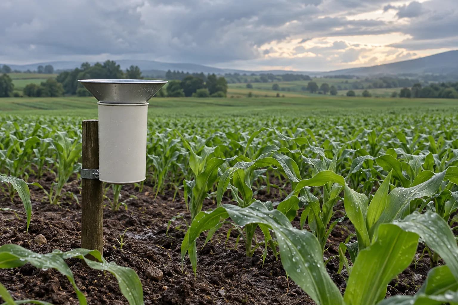
Keep rainfall records useful through an outage
Agree measurement timestamps, local storage and recovery before selecting a station.
Explore this requirement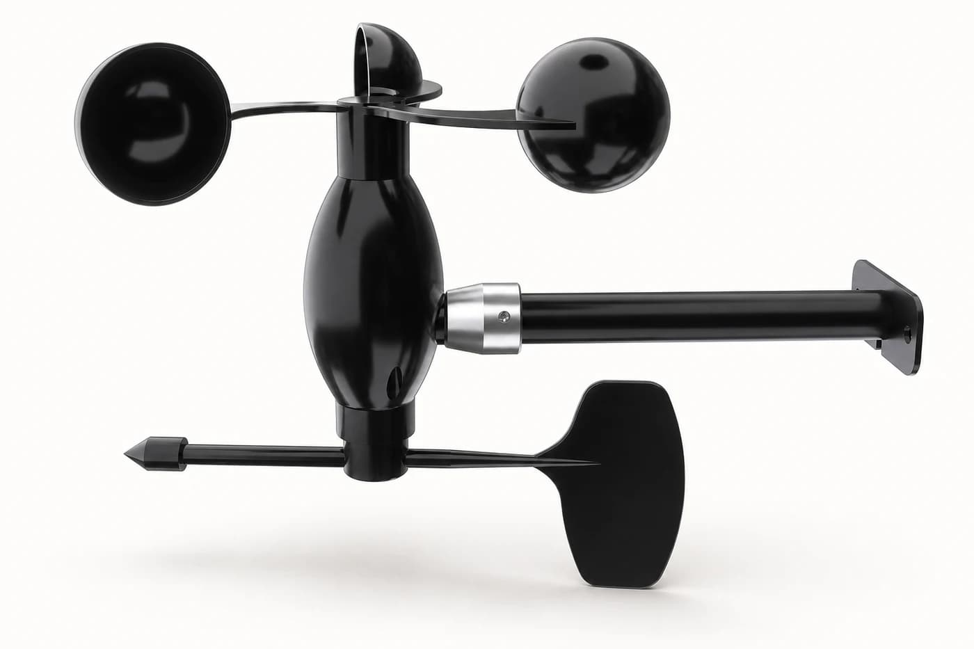
Integrated cup anemometer and wind vane with selectable 0–30, 0–50 or 0–60 m/s range and one RS485, 4–20 mA or voltage output configuration.
Appearance, connectors and included accessories follow the configuration confirmed in your quotation.
Related application hardware: Environmental Monitoring
Share your current model, a photo or the connection you need. We help assess interfaces, power and the required configuration.
Get selection & integration helpPublic documents describe this product family and selection options. Wiring, register maps and compliance documents must match the model and version selected for your order.
English · Web page · printable
Current online selection reference
Agriculture & Weather Hardware Catalog
PDF · English · 447 KiB
File revision: 2026-07-22 · afc637605e57
Choose what you need. We first identify the model and revision, then confirm which documents can be supplied. The request does not imply that every document is available.
Compare uses, interfaces and configuration options. These are selection references.
An SG code helps identify a sourcing option; it is not a substitute for the manufacturer model or its certificate.
Confirm the exact model, configuration, photograph, document revisions, accessories, price, delivery and warranty.
Start with a short description. A complete equipment list is not required.
Agree measurement timestamps, local storage and recovery before selecting a station.
Explore this requirement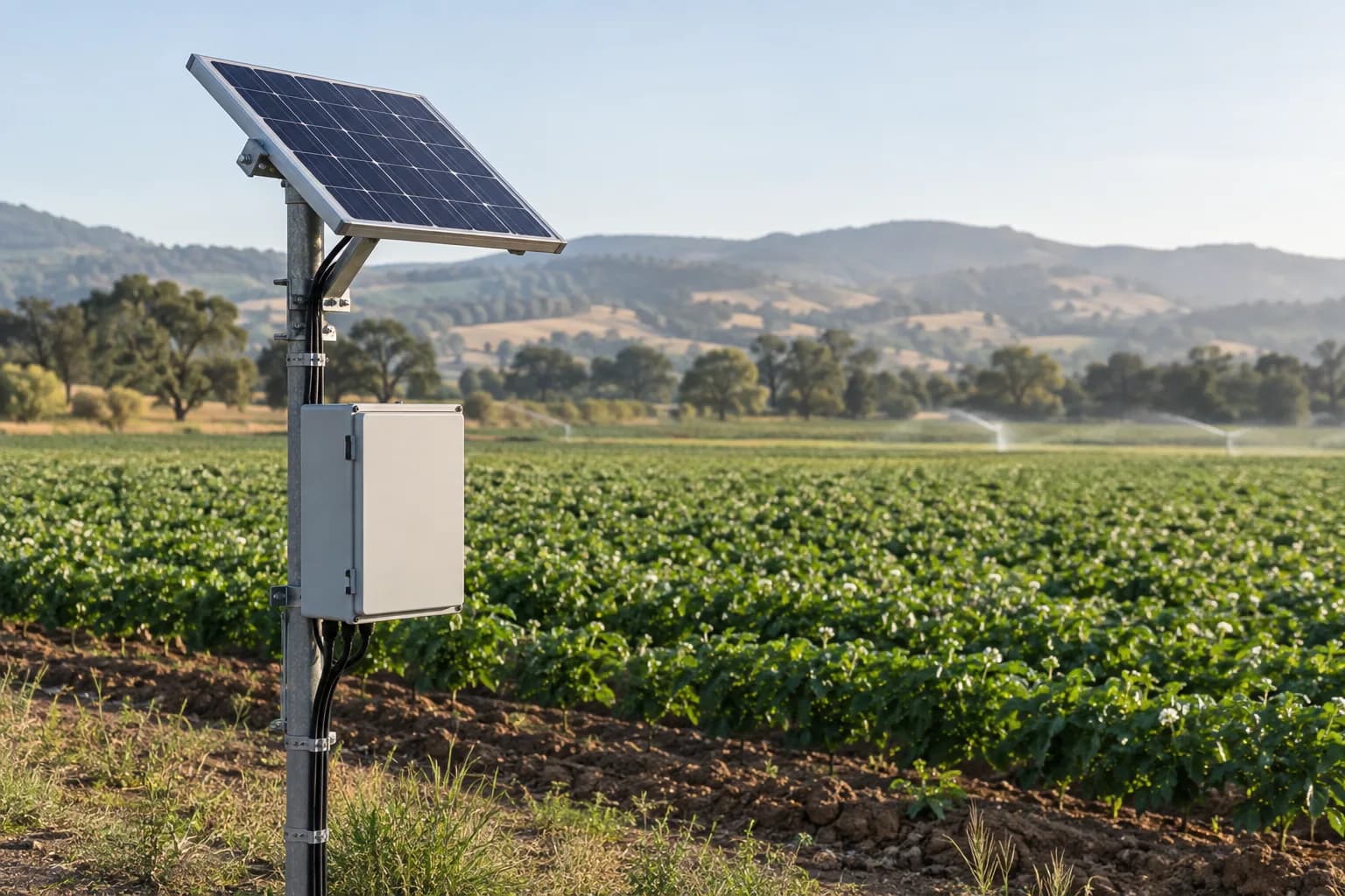
Size field power around the final equipment load, seasonal sunlight and visit interval.
Explore this requirementSystem design, software integration, PLC/SCADA programming and site installation responsibilities are agreed in the written project scope.
Data destination
Customer platform or an agreed third-party service
The written quotation ties the site requirement to one reviewed hardware configuration.
Site requirement
Application, medium, mounting and environment
Hardware configuration
Signal, protocol, power and enclosure
Quote confirmation
Model, quantity, certificates and delivery
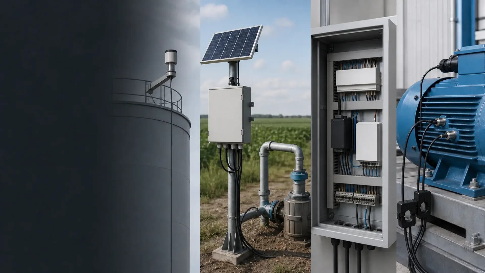
Remote integration context
Sensors, interfaces, enclosure, power and mounting are confirmed against the actual project before quotation.
The reviewed manual covers one integrated cup-and-vane sensor family with several mutually exclusive electrical configurations.
Model-selection reference
Compare equipment options in this catalog section.
24 sourcing references from “Wind speed and direction sensors”. Put an SG code in the RFQ so we can match the same catalog row.
SG-WND-103SG-WND-102SG-WND-104SG-WND-105SG-WND-106SG-WND-107SG-WND-108SG-WND-109SG-WND-110SG-WND-111SG-WND-112SG-WS-112SG-WS-113SG-WS-114SG-WS-128SG-WS-149SG-WS-155SG-WND-115SG-WND-116SG-WND-117SG-WND-118SG-WND-119SG-WND-120SG-WND-101Compare adjacent hardware families for the same monitoring path.
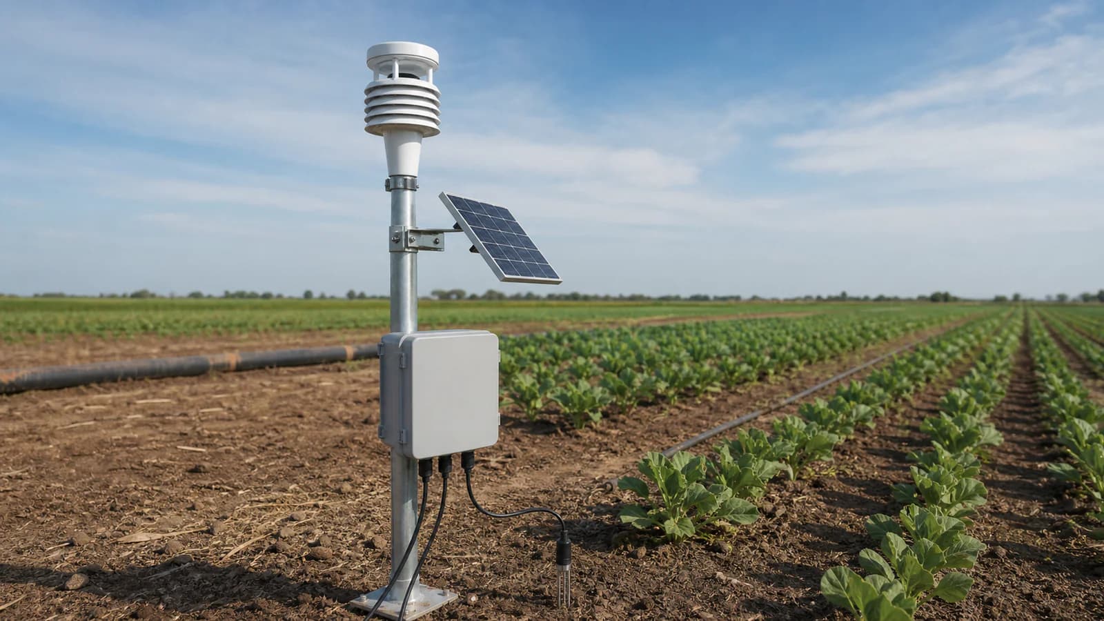
Use this integrated mechanical sensor when one mast position must provide both wind speed and 0–360° direction to a logger, PLC or RTU. Select one wind-speed range, one output type and the matching DC supply before quotation; the analog and RS485 variants are alternatives, not simultaneous outputs.
No. The reviewed manual describes alternative output configurations. Select one of RS485 Modbus RTU, 4–20 mA, 0–2 V, 0–5 V or 0–10 V when the product is quoted.
The reviewed range options are 0–30, 0–50 and 0–60 m/s. One range is selected for the ordered configuration. The reviewed starting wind speed is no more than 0.3 m/s.
RS485 and 0–2 V configurations use 5–24 VDC. The reviewed 0–5 V, 0–10 V and 4–20 mA configurations use 12–24 VDC. An optional heater requires a separate 12–24 VDC supply budget of 15 W average and 18 W peak.
Provide mast height, boom geometry, orientation, cable route, nearby obstructions, grounding, surge protection and icing or salt exposure. These details affect placement, maintenance and whether the optional heater is appropriate.
Wind speed / direction requirement and range; Low-wind threshold and icing / salt / dust conditions; Output and connected logger / RTU; Mast height, boom, orientation and cable length
Open the Agriculture & Weather Hardware Catalog linked on this page. Use it to compare equipment options before requesting a configuration.
Compatibility is reviewed against your field signals, protocols and upstream platform. Typical pairings include RS485 Modbus RTU masters using the selected 9600 baud, 8N1 configuration, Analog inputs accepting one selected 0–2 V, 0–5 V, 0–10 V or 4–20 mA signal configuration, Weather loggers, PLCs and field RTUs that can scale separate wind-speed and direction values.
Product-family reference. Final ordered model and specifications are confirmed in the written quotation.