Water delivery across the farm
Connect level, flow and pump status with the water decisions your team makes.
Explore this requirement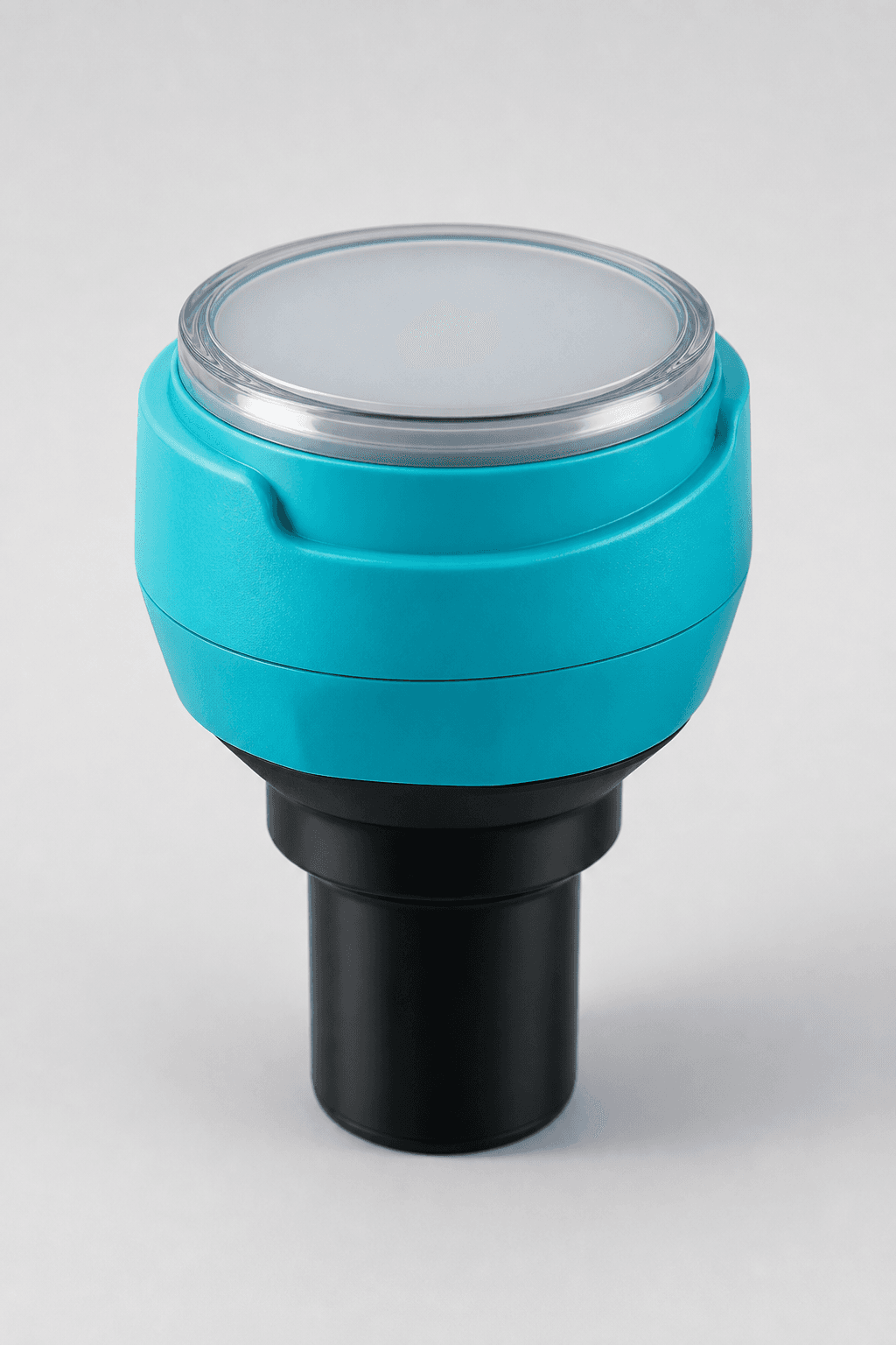
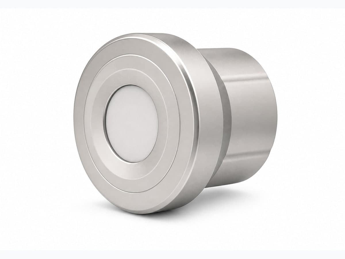
Integrated non-contact liquid-level transmitter with selectable 5 to 30 m ranges and 4-20 mA or RS485 Modbus RTU output.
Appearance, connectors and included accessories follow the configuration confirmed in your quotation.
Related application hardware: Water Monitoring
Share your current model, a photo or the connection you need. We help assess interfaces, power and the required configuration.
Get selection & integration helpPublic documents describe this product family and selection options. Wiring, register maps and compliance documents must match the model and version selected for your order.
English · Web page · printable
Current online selection reference
Water & Utilities Hardware Catalog
PDF · English · 388 KiB
File revision: 2026-07-22 · 82cac85fcd00
Choose what you need. We first identify the model and revision, then confirm which documents can be supplied. The request does not imply that every document is available.
Compare uses, interfaces and configuration options. These are selection references.
An SG code helps identify a sourcing option; it is not a substitute for the manufacturer model or its certificate.
Confirm the exact model, configuration, photograph, document revisions, accessories, price, delivery and warranty.
Start with a short description. A complete equipment list is not required.
Connect level, flow and pump status with the water decisions your team makes.
Explore this requirement
Review coverage, equipment identity and the path into your chosen platform.
Explore this requirementSystem design, software integration, PLC/SCADA programming and site installation responsibilities are agreed in the written project scope.
Data destination
Customer platform or an agreed third-party service
The written quotation ties the site requirement to one reviewed hardware configuration.
Site requirement
Application, medium, mounting and environment
Hardware configuration
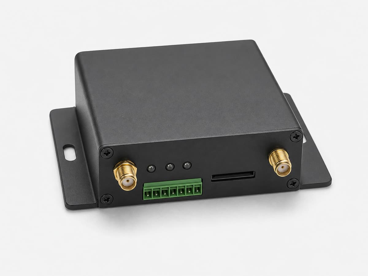
Signal, protocol, power and enclosure
Quote confirmation
Model, quantity, certificates and delivery
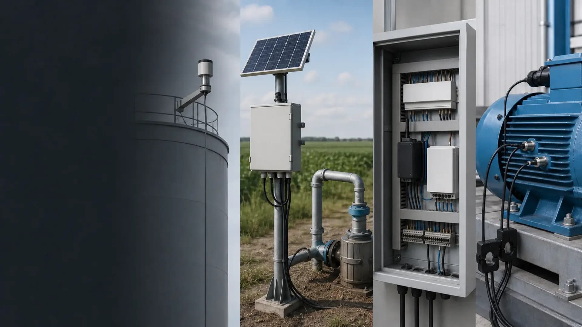
Remote integration context
Sensors, interfaces, enclosure, power and mounting are confirmed against the actual project before quotation.
The reviewed specification supports an integrated non-contact transmitter, but site conditions determine whether the echo will remain stable.
Model-selection reference
Compare equipment options in this catalog section.
9 sourcing references from “Radar and ultrasonic non-contact level transmitters”. Put an SG code in the RFQ so we can match the same catalog row.
SG-RLT-101SG-RLT-102SG-RLT-103SG-RLT-104SG-RLT-105SG-ULT-102SG-ULT-103SG-ULT-104SG-ULT-101Compare adjacent hardware families for the same monitoring path.
Use this integrated transmitter when liquid level can be measured from above without contact and the sensor has a clear acoustic path to the surface. The range, blind zone, process connection, output and power option are selected together. Foam, heavy vapour, turbulence, internal structures or strong temperature gradients must be reviewed before ultrasonic measurement is released for the site.
More guides
The reviewed configurations are 5, 10, 15, 20 and 30 m. The blind zone, probe size and threaded process connection depend on the selected range, so the mounting height and maximum liquid level are confirmed before quotation.
The reviewed output options are 2-wire 4-20 mA, 4-wire 4-20 mA and 4-wire RS485 Modbus RTU. The reviewed supply options are 24 VDC or 220 VAC, with 12 VDC available only on the RS485 configuration. The ordered combination is confirmed in the quotation.
Heavy foam, bubbles, steam, mist, turbulent surfaces, internal obstructions or a mounting angle that is not perpendicular can produce weak or false echoes. Share the tank geometry and surface conditions so ultrasonic, radar or hydrostatic measurement can be compared before selection.
Mounting height, maximum liquid level and required measuring range; Tank / channel dimensions, medium and process connection; Foam, bubbles, vapour, turbulence, temperature change and internal obstructions; Required 4-20 mA or RS485 Modbus RTU output and connected PLC / RTU / gateway
Open the Water & Utilities Hardware Catalog linked on this page. Use it to compare equipment options before requesting a configuration.
Compatibility is reviewed against your field signals, protocols and upstream platform. Typical pairings include PLC, RTU or data-acquisition inputs accepting 4-20 mA, RS485 Modbus RTU masters on the selected communication configuration, Tank, reservoir, well-head and open-channel mounting arrangements reviewed for a clear acoustic path.
Product-family reference. Final ordered model and specifications are confirmed in the written quotation.