
Design example
Solar Site Weather and Inverter Monitoring
Compare weather and irradiance readings with inverter or meter data for a solar-site monitoring plan.
Design example: use the site requirements and equipment path below to plan your own configuration.
Hardware in this guide
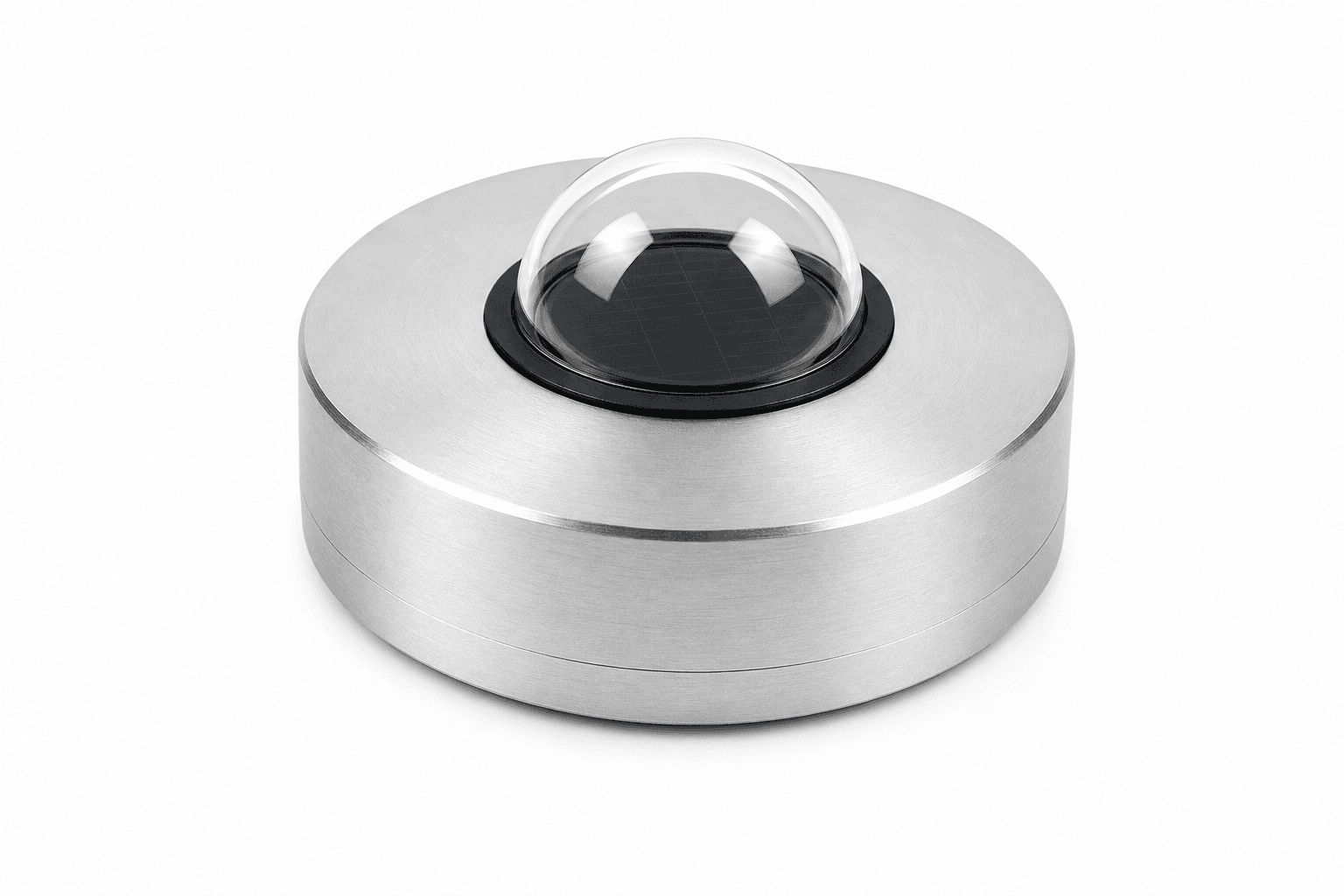
Class C Pyranometer for Solar Radiation Monitoring
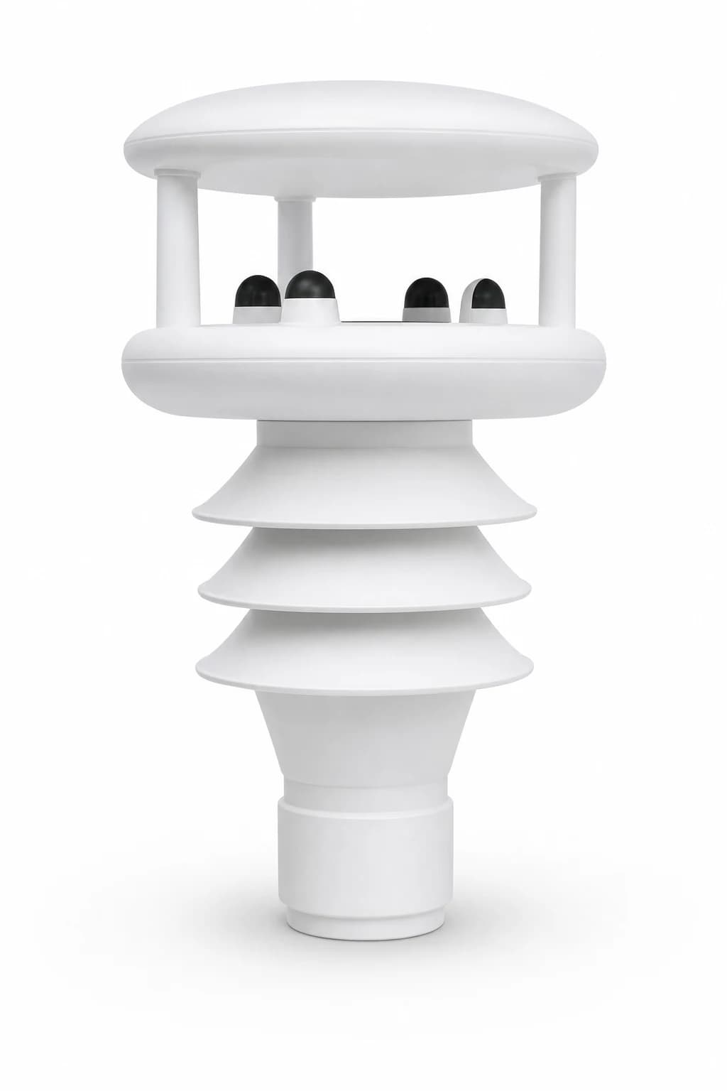
Ultrasonic Weather Station
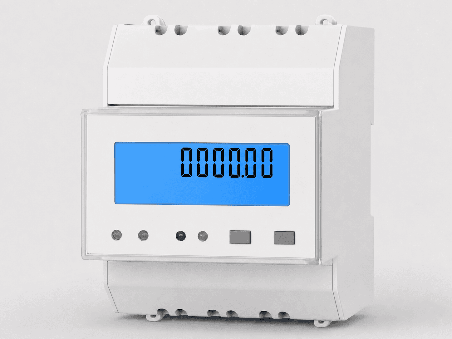
DIN-Rail Three-Phase Energy Meter
Product-family photos. See each product page for specifications and options.
Planning a similar site?
Send the site count, signals, network, power and reporting target. We will return a comparable hardware configuration for quotation.
Site conditions to check
Compare power, communication and equipment requirements for irrigation, pumps, soil and weather monitoring.
agri.sungeneindustrial.com
Agricultural irrigation and farm pumps
Compare pump contacts, motor current and water flow before choosing what to monitor at your farm.
agri.sungenegroup.com
Farm water, soil and weather monitoring
Plan field and orchard measurements around available power, coverage and maintenance visits.
Project team
A solar project team evaluating field telemetry for performance analysis.
Challenge
The project needs weather and irradiance context alongside generation readings. The inverter, meter and weather instruments have separate interfaces to check.
Equipment in the system
Example equipment arrangement. Check compatibility and agree who handles software, PLC/SCADA programming and site installation.
Data destination
Customer platform or an agreed third-party service
Site context
- Solar field or rooftop project
- Weather and irradiance data needed
- Meter or inverter protocol available for review
Approach
- Collect weather and irradiance as performance context
- Confirm inverter or meter protocol separately
- Map data into customer EMS or dashboard fields
Hardware plan
- Solar radiation sensor
- Weather station
- RS485 meter or inverter input
- 4G/Ethernet gateway
Hardware reference
Product-family photos; the model and enclosure may vary.
Integration path
- Modbus RTU sensor chain
- MQTT or Modbus TCP handoff
- Alarm fields for weather, power and offline state
Checks before rollout
- Compare generation data with time-aligned weather and irradiance readings
- Check each instrument interface before selecting the gateway
- Test the complete equipment, accessories and data mapping at the pilot site
Quote inputs
- Sensor mounting plan
- Meter/inverter protocol
- Backend endpoint
- Target reporting interval
Related pages
FAQ
How can I use this design example?
Compare the measurement points, equipment connections and site checks with your project. Send the existing devices, available power and receiving system so we can check a suitable configuration.
Can weather, irradiance and inverter data share a gateway?
They can when the selected gateway supports each instrument’s interface and polling requirements. Confirm the weather-sensor outputs and inverter or meter registers separately, then map the required values to the receiving EMS or application.
What should be checked in a solar-site telemetry pilot?
Check sensor mounting, units, timestamps, reporting interval and loss-of-connection states. Send the mounting plan, meter or inverter protocol and receiving-system requirements so the gateway and accessories can be selected together.